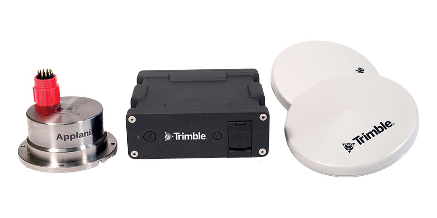

A-2-Sea deployed the Trimble Applanix POS MV OceanMaster on the Noortruck to support hydrographic survey operations. This system integrates inertial navigation with GNSS positioning to provide accurate motion compensation and positioning data, ensuring precise measurements over extended lever arms.
As with any new vessel charter, careful planning of sensor placement was required to optimize system performance. The positioning of GNSS antennas, IMUs, and sonar equipment directly affects the quality of hydrographic data collection.
A comprehensive dimensional control survey, sensor calibration, and equipment verification process was conducted to ensure accurate and reliable data acquisition.
Installing the Inertial Measurement Units (IMUs)
To ensure redundancy, A-2-Sea identified two IMU locations on the vessel. The primary IMU was installed in a secure location, elevated above the deck and positioned close to both the centerline and the vessel’s center of rotation.
A-2-Sea’s design engineers measured and designed an aluminum plate and box to support, secure, and protect the IMU. The Applanix base plate was then secured onto the aluminum plate before being enclosed.
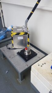
Figure 2: Applanix IMU mounting location featuring protective covering and cable routing solution.
A secondary IMU location was identified in the cofferdam space (under the wheelhouse), selected for its secure, protected position near the vessel’s centerline and center of gravity. Positioning this location close to the entrance to the cofferdam allowed for a clear line-of-sight access for the dimensional control survey. Again, an aluminum plate was designed by A-2-Sea engineers as an intermediate plate between the cofferdam deck and the IMU plate. The secondary location provided redundancy should any issues arise with the primary installation.
The Applanix mounting plate is a bespoke design capable of accommodating multiple IMU types. This design principle allows surveyors to measure the mounting plate, enabling IMUs to be swapped out without the need to re-survey misalignment angles or offsets. A-2-Sea had the advantage of two locations and two mounting plates, offering additional flexibility.
Installing the GNSS Antennas
The Applanix POS MV OceanMaster utilizes the GNSS Azimuth Measurement Subsystem (GAMS) to assist the IMU in heading calculations. This feature employs two GNSS antennas to determine a GNSS-based heading accurate to 0.01 degrees when combined with the inertial navigation solution.
To optimize antenna placement, A-2-Sea engineers designed a secure and rigid mounting structure, ensuring minimal external interference. Multiple antenna mount points were made available and measured to provide different options and backups.
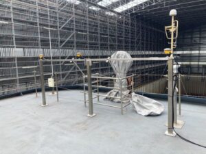
Figure 3: A-2-Sea designed an antenna mounting frame to provide an optimal location for GNSS data reception.
The Dimensional Control Survey
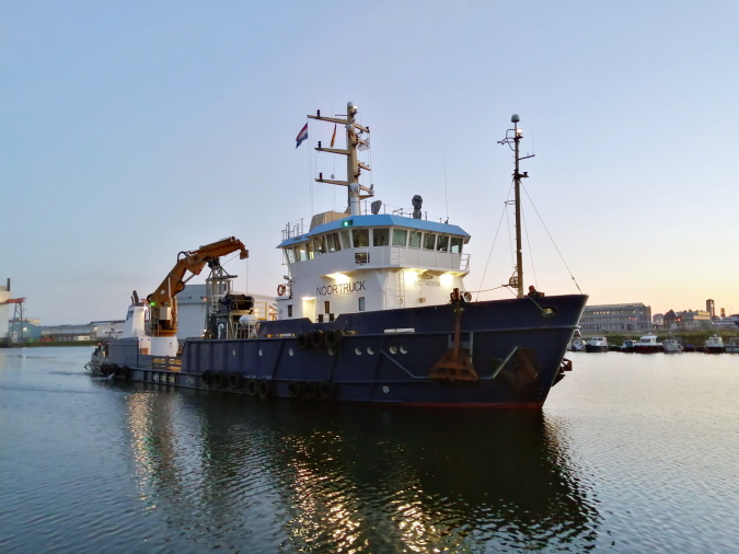
The installation on the Noortruck occurred while the vessel was in dry dock, ensuring a stable platform for executing a precise Total Station Dimensional Control Survey.
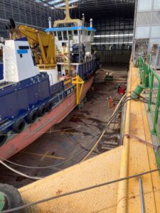
Figure 4: A surveyor conducting a dimensional control survey of the Noortruck.
Surveyors used the technique of defining a vessel reference frame (VRF) before establishing sensor locations and orientations relative to it. A Common Reference Point (CRP) was established as a target on the IMU housing, with all sensor offsets measured relative to this position. Additionally, the vessel’s Center of Rotation (COR) was defined, which is critical for accurate heave measurements.
All Total Station coordinates were measured within ±0.5mm for each ordinate. These values were obtained through multiple station setups, with the mean computed, resulting in an average standard deviation of 0.5mm.
Permanent and recoverable control points were established throughout the vessel within a specified tolerance of ±0.01m relative (at the 95% confidence level) in X, Y, and Z. Similarly, all sensors were positioned within the VRF with a tolerance of ±0.02m relative (at the 95% confidence level) in X, Y, and Z.
The final step was to determine the IMU frame relative to the vessel frame. By extending the baseline of the IMU plate, the misalignment angles were determined. The IMU mounting plate has precisely machined grooves along the X and Y axes, allowing a bar to be placed along these edges to increase the baseline length for measuring the mounting angle. The longer this baseline, the more precisely the angular component can be computed from the 3D coordinate values.
The Verifications
GAMS Verification
During the Dimensional Control Survey, the primary and secondary antenna locations were precisely measured, and the X, Y, Z baseline vector components determined.
To verify these measurements, a dynamic GAMS calibration was performed at sea. By starting with zero values in the GAMS parameter setup, a series of dynamic maneuvers allowed the POS MV to automatically compute the GAMS parameters. The results closely aligned with the values obtained from the dimensional control survey.
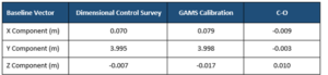
Table 1: Comparison of GAMS baseline vectors from the dimensional control survey and dynamic GAMS calibration. Small residuals validated the dimensional control-derived figures.
The values from the Dimensional Control Survey were used moving forward as they were deemed more precise. The dynamic GAMS calibration relies on high-quality GNSS measurements and sufficient vessel dynamics, which can be difficult to achieve on larger vessels. As a result, the GAMS calibration process served as a validation step to check for errors in the dimensional control survey.
Position Verification
While alongside, position checks were carried out using RTK-enabled Leica GNSS receivers. The GNSS antennas were placed at previously measured control points, and position data was logged. These control points were also integrated as nodes within the QPS QINSy software, where POS MV data was interfaced.
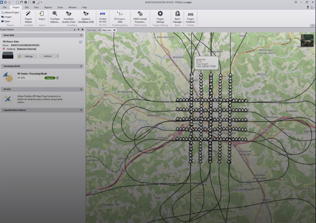
The POS MV utilized real-time Trimble RTX® correction service data delivered over L-Band to achieve centimeter-level accuracy.
Trimble RTX is a globally available network providing real-time centimeter accuracy through satellite measurements, a global tracking station network, advanced atmospheric models, and correction algorithms
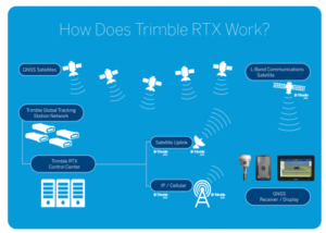
Figure 5: Trimble RTX, a globally available network providing centimeter-level corrections via L-band satellite and the Internet.
A comparison of RTK GNSS data with POS MV GNSS-aided inertial data, referenced within QINSy nodes, showed a close agreement, meeting the project specification.
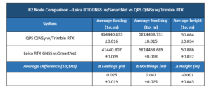
Table 2: Position verification results comparing RTK GNSS with POS MV position solution.
With the POS MV installed, calibrated, and verified, further project-specific sensor calibrations were conducted.
Other Projects
The Noortruck also conducted nautical charting operations for the Civil Hydrography Program off the East Coast of the UK.
In collaboration with Applanix, Trimble, and A-2-Sea, Trimble RTX was activated over L-Band through POSView, the control software for the POS MV OceanMaster. The system achieved centimeter-level accuracy within minutes of activation, allowing A-2-Sea to perform calibrations and verifications while maintaining an accurate real-time positioning solution during survey operations.
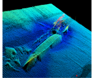
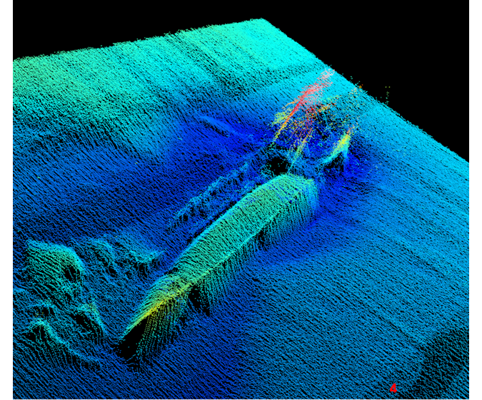
Figure 6: Multibeam data showing a distinct seabed feature, validated using the POS MV OceanMaster and Trimble RTX.
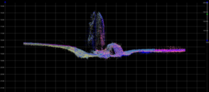
Figure 7: Multibeam swath alignment confirming accurate angular calibration during the Multibeam Patch Test.
Conclusion
A-2-Sea successfully mobilized their Applanix POS MV OceanMaster on the Noortruck, ensuring optimal sensor placement, conducting a rigorous dimensional control survey, and verifying sensor calibrations. This resulted in the acquisition of high-quality hydrographic data.