
Silicon Designs has shared a practical guide on how to calibrate its DC accelerometers, in differential mode, ensuring accuracy and confidence in data gathered at sea.
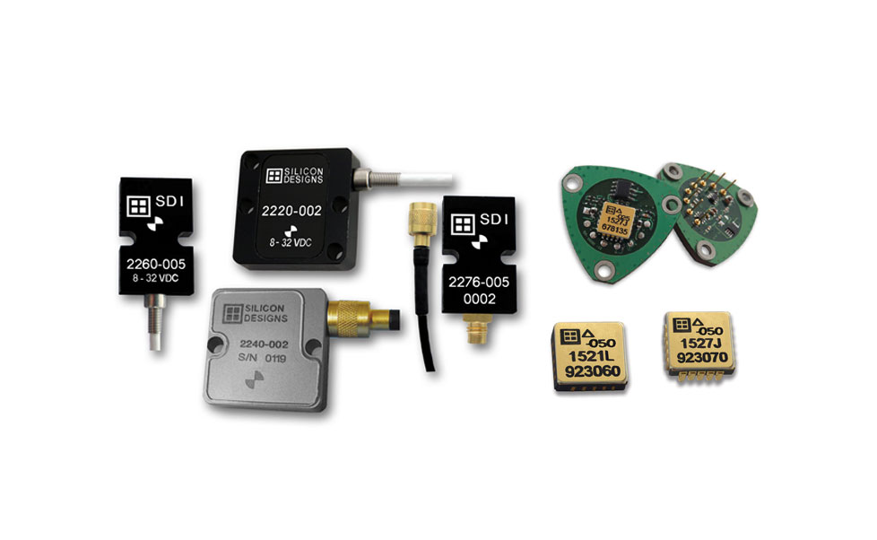
Silicon Designs accelerometers use MEMS capacitive sensing technology and respond to Earth’s gravity, enabling them to approximately measure about 1G when stationary and level. This characteristic makes it possible to perform a straightforward static calibration, valuable for ocean science applications where instruments must deliver reliable results in challenging environments.
Auto-Calibration with G-Logger®
The article explains how calibration can be automated using Silicon Designs’ G-Logger® Models 3330 and 3340. These systems not only record live and stored data but also include an auto-calibration function for up to three channels. By providing power directly, they remove the need for an external supply and can be paired with SDI’s test kits to simplify setup.
Recommended Equipment
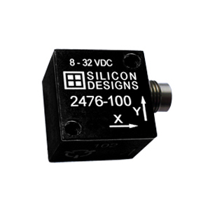
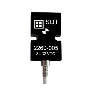
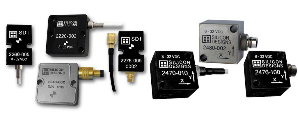
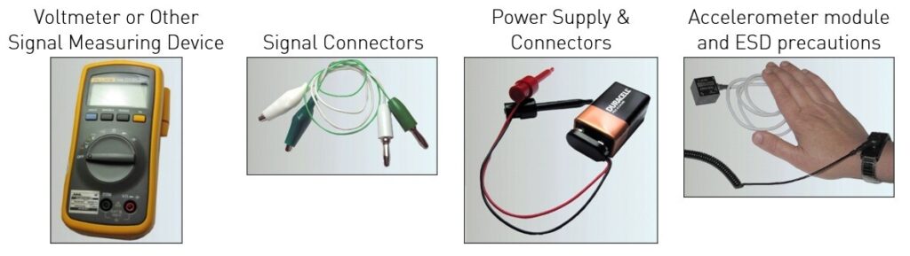
The example provided uses the 2260-025 Industrial Test & Measurement module, but the same process applies across SDI’s accelerometer range, including triaxial modules and surface-mount designs when paired with EB-L or EB-J test kits.
Calibration Procedure
For manual calibration, users connect the accelerometer as directed in the Quick Start Guide, commonly with a 9V DC power source. By placing the module in the +1G position (lid up) and -1G position (lid down), output voltages can be recorded.
Key Calculations The article then shows how to calculate:
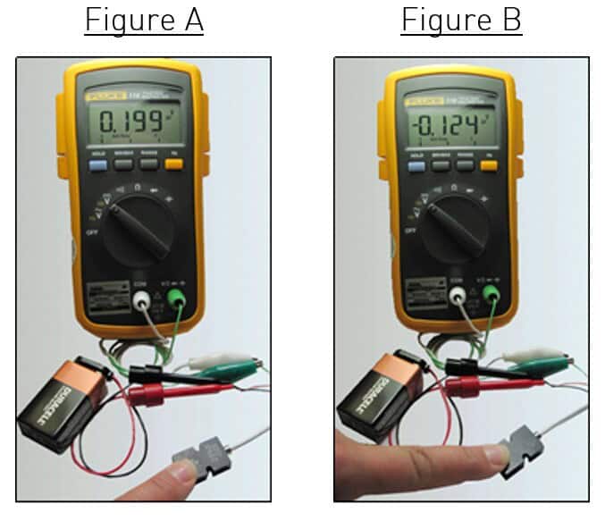
- 0G Bias: Average of +1G and -1G readings
- Scale Factor: Half the difference between +1G and -1G readings
- Sensitivity: Based on output span and g-range, typically expressed in mV/G
Worked examples demonstrate how these calculations provide precise performance data.
Readers interested in step-by-step instructions, formulas, and example calculations can find and download the full guide on the Silicon Designs website: Calibrate Your SDI Accelerometer